Posts

Showing posts from 2017

Featured post

Types of mechanical forces

A force exerted on a body can cause a change in either the shape or the motion of the body.The unit of force in SI system is the Newton(N) and CGS system is dyne.No solid body is perfectly rigid and when force are applied to it,changes in dimension occur.such changes are not always perceptible to the human eye since they are negligible. For the example,The span of a bridge will sag under the weight of a vehicle and a spanner will bend slightly when tightening a nut. It is also important for civil engineers and designers to appreciate the effects of forces on materials.Together with their mechanical properties of the materials. There three main types of mechanical forces that can act on a body.They are 1)Tensile force 2) compressive force and 3) shear force

Ultrasonic welding:

Image
Ultrasonic welding is a cold-joining process(I.e.,solid- state welding).In this case ,a bond is produced by ultrasonic vibratory energy in the weld region.The equipment necessary for ultrasonic welding is shown in fig.It includes a transducer,a velocity transformer with a sonotrode tip and a suitable anvil.The prob induces lateral vibrations on workpieces such that surface films are broken and bond results due to slip between clean surfaces under pressure.The operation should be stopped as soon as weld is complete. This is to avoid bonding of prob with upper workpiece. ADVANTAGES: 1) Absence of generated heat. 2) Dissimilar metals can be joined. 3) No oxidation and distortion 4) The welding time is only about one second or less. DISADVANTAGE: 1) The maximum thickness is limited to 0.3 to 2.5mm APPLICATIONS: The ultrasonic welding is employed for spot welding and seam welding of thin strips or foils.It can also be used for welding aluminium up to 2.5mm thick.The

SUBMERGED ARC WELDING:

Image
Submerged arc welding is used for the production of long continuous weldings.In this case,a bare electrode (1.5-10mm) in the form of continuous wire is used; and the arc is struck between electrode wire and work piece under the flux,consisting of lime,silica,magnesium oxide,calcium fluoride and other elements.The flux is fed as a powder in front of the electrode.the flux near the arc melts and forms a protective coating of slag, which is easily detached from finished weld.The rate of cooling of the weld metal is slow,and it is also protected from atmosphere while cooling.The principle of submerged arc welding is shown in fig.In this case,an automatic feeding device ensures that the gap between the electrode and the base metal is constant.Electric current usually range between 300A and 2000A.The power supply is from a standard single or three phase power lines with a primary rating up to 440V. ADVANTAGES: The process offers the following advantages: 1)High rate of deposi

METHODS OF APPLICATIONS OF CUTTING FLUIDS :

Image
The method of application of a cutting fluid is very important and depends on the particular operation. These methods vary from hand applications such as use of brush or oil-can to high pressure applications.For high production. The following methods are used.    1)Flood method,    2) Jet method,and    3) Mist method. 1) Flood method : In this method,a reciprocating pump is used to force the coolant over the work and tool.The outlet of the pump is connected to a nozzle through flexible pipe.The nozzle can be adjusted to direct the stream of the fluid at the cutting zone.This is the most common method of application of cutting fluid. 2) jet method : In jet method,a small jet of fluid at high speed is directed at the point of metal separation from the underneath the tool.In high-speed jet system gear or vane type pump is used to maintain high pressure. 3) Mist method : In mist method,the fluid is passed through a specially designed nozzle to form very fine drop

METHODS OF LUBRICATION:

Various methods are used to apply the lubricant to the machine tools.Lubricating oil is generally applied to sliding parts with the help of oil-can.Lubricants are also applied by the following systems.        1)Gravity feed system.        2) Pressure feed system. In the gravity feed system lubricant is applied to the sliding parts through oilcups which are located at the higher levels of sliding parts l.In this oil flows to the parts due to gravity. Pressure feed system is generally used in automobiles where lubricants are applied under pressure by using oil pump which is situated below the engine.

Law of conservation of energy:

Image
Total energy in a system is constant.Energy cannot be created cannot be destroyed but one form of energy is converted into another form

ADVANTAGES AND LIMITATIONS OF BROACHING:

Broaching is an interesting machining process which is used in mass production. It has certain advantages and limitations as compared to the other machining processes.these are given below. ADVANTAGES : 1) Fast and simple process. 2)High degree of accuracy and finish is possible. 3)Any shape of profile can be easily machined. 4) Machining process is completed with one stroke of broach. 5) Life of broach tool is high. 6)Cutting temperature and tool wear is low. 7) Doesn't require a highly skilled operator. 8)Cutting force acts in the clamping direction I.e.,it doesn't tends to lift the workpiece from fixture. 9)cutting fluids can be applied more easily and effectively. 10)Most economical for mass production of components. LIMITATIONS: 1) Not economical for small quantity productions. 2)Cost of broach is high. 3) Tool grinding (broach sharpening) is difficult and expensive. 4) Not suitable to machine a surface having obstruction. 5) The work m

APPLICATIONS OF BROACHING :

Image
The operation of broaching was originally developed for machining small,internal surfaces such as key way in a small diameter which is relatively difficulty for slotter.Broaching is widely used in present day industry for machining a large variety of jobs which were formerly milled or shaped. Internal broaching is used for machining and sizing of round holes,square,hexagonal,and many other shapes of holes.Internal keyways,splines and gears are easily produced by broaching.External or surface broaching is increasingly used in mass production as an alternatively to milling.It can machine plane or complex shapes easily and economically.

CLASSIFICATION OF BROACHING :

According to method of operation broaching is classified as follows 1) Pull broaching     -The broach is pulled through stationary        work. 2) Push broaching     - The broaching is pushed through                      stationary work 3) Surface broaching     - The broach moves across the work or              vice versa. 4) Continuous broaching     - The work is moved continuously against        stationary broaches.

PRINCIPLE OF BROACHING MACHINE:

Image
In broaching, the broach is pushed or pulled over a external flat surface of a stationary workpiece. In internal broaching the broach is pushed or pulled through the hole in the stationary workpiece.In certain machines,the braich is held stationary and the workpiece translates over the broach.For broaching no separate feed is required as the feeding action is in built in the teeth form.Each successive tooth is a little higher than the one preciding it.Therefore each tooth removes a layer of workpiece material.The first fee teeth on broach are low to permit the small end of the tool to be passed through work.The intermediate teeth remove the most of the metal; and the last few teeth finish the surface to size machining operation completes in one pass of the broach.The cutting action of broach teeth is shown in fig.

PROPERTIES OF CUTTING FLUIDS:

To get the optimum benefits, the cutting fluid should possess the following qualities. 1) They should possess good lubricating properties to minimise the friction. 2)They should possess high heat absorption capacity so as to carry away the heat generated. 3)They should present no fire or accidental hazards. 4) They should not cause skin irritation. 5)They should not emit obnoxious odours and vapours harmful to the operator, workpiece or surrounding area. 6) They should be of low viscosity to permit free flow and easy separation from chips collected. 7)They should prevent rusting of the Machine slidings and working surfaces. 8) They should be suitable for a variety of cutting operations, and should be easily available at low price so as to minimise production cost. 9) They should be chemically stable. 10) they should not deteriorate in storage. 11) They should have high flash point.

CUTTING SPEED,FEED AND DEPTH OF CUT IN PLANER MACHINE

CUTTING SPEED: The cutting speed in planing is the speed of the work in the direction of cutting motion when the metal is being cut. it is expressed in m/min. FEED: The feed in planer is the distance the tool head moves at the beginning of each cutting stroke.it is expressed in mm per full stroke (double stroke). DEPTH OF CUT: Depth of cut is the thickness of metal removed in one cut or pass.it is measured in the direction perpendicular to the machined surface.it is expressed in mm.

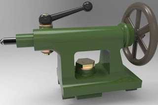
Tailstock

Image
The tailstock is located on right side of the bed i.e.right hand side of the operator. The main purpose of a tailstock on an engine lathe is to support free end of a work during operation.it is also used to hold tools for making holes (twist drills,reamers) adjusted along the bed of the lathe accommodate different lengths of stock.it is provided with set over screw at its base for taper turning alignment.it has cast iron body with bore to accommodate tailstock spindle,and the top portion contains the spindle,tailstock hand wheel, and a spindle clamp for locking the spindle in position. The end of the spindle has a taper bore for holding dead centre,taper shank drills and other tools.the spindle can centre,taper shank drills and other tools.The spindle can be moved in and out of the tailstock by the rotation of hand wheel in anticlockwise and clock wise direction respectively.A tailstock is shown in fig.

What is absorbent

A material which, due to an affinity for certain substances, extracts one or more such substances from a liquid or gaseous medium with which it contacts and which changes physically or chemically, or both, during the process. Calcium chloride is an example of a solid absorbent, while solutions of lithium chloride, lithium bromide, and ethylene glycols are liquid absorbents.

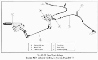
Emergency break.

Image
In cars,emergency brake is a latching brake usually used to keep the vehicle stationary. It is sometimes also used to prevent a vehicle from rolling when the operator needs both feet to operate the clutch and throttle pedals.

Rack-and-pinion

Image
A rack-and-pinion is a type of linear actuator that comprises a pair of gears which convert rotational motion into linear motion. A circular gear called "the pinion" engages teeth on a linear "gear" bar called "the rack", rotational motion applied to the pinion causes the rack to move, thereby translating the rotational motion of the pinion into the linear motion of the rack.

What is Air bag?

Image
A safety device fitted inside a road vehicle, consisting of a cushion designed to inflate rapidly and protect passengers from impact in the event of a collision.

What is crank shaft.

Image
A crankshaft is a mechanical part able to perform a conversion between reciprocating motion and rotational motion. In a reciprocating engine, it translates reciprocating motion of the piston into rotational motion, whereas in a reciprocating compressor, it converts the rotational motion into reciprocating motion. In order to do the conversion between two motions, the crankshaft has "crank throws" or "crankpins", additional bearing surfaces whose axis is offset from that of the crank, to which the "big ends" of the connecting rods from each cylinder attach.

What is bolt and nut.

Image
A pair of objects with matching screw threads. When either the bolt or the nut is turned, it moves with great force. Often used as fixing devices. The nut is the circular piece that looks like a ring with threads on the inside hole. The bolt is the shaft with threads.

Fuel supply system in diesel engine

Image
F uel supply system is a seperate system used to deliver diesel at correct time in correct quantity, to a diesel engine (or  C.I  engine), for smooth and efficient operation. The operation of a diesel engine is different from that of a petrol engine. In a petrol engine, air-fuel mixture is supplied by a carburetor to the engine, at the beginning of the suction stroke. But in a diesel engine, fuel (without air) is supplied at the end of the compression stroke, by means of a fuel supply system. Fuel supply system is the food pipe of a vehicle. Diagram of fuel supply system in diesel engine: Components: Fuel supply system in diesel engine is made of the following components: Diesel tank or reservoir Low pressure pump Filter Fuel injection pump Fuel injectors 1. Diesel tank or reservoir: Whenever you supply fuel to a diesel engine vehicle, it is stored in the diesel tank. Diesel tank temporarily stores diesel that is to be supplied to the engine. 2. Low pressur

Two stroke engine

Image
Edit Watch this page Read in another ll Page issues A  two-stroke , or  two-cycle ,  engine  is a type of  internal combustion engine  which completes a power cycle with two strokes (up and down movements) of the  piston  during only one crankshaft revolution. This is in contrast to a " four-stroke engine ", which requires four strokes of the piston to complete a power cycle. In a two-stroke engine, the end of the combustion stroke and the beginning of the compression stroke happen simultaneously, with the intake and exhaust (or  scavenging ) functions occurring at the same time. Two-stroke engines often have a high  power-to-weight ratio , power being available in a narrow range of rotational speeds called the "power band". Compared to four-stroke engines, two-stroke engines have a greatly reduced number of moving parts, and so can be more compact and significantly lighter.

Four stroke petrol engine

Image
Four-stroke cycle used in gasoline/petrol engines.  1  = Intake,  2  = Compression,  3  = Power,  4  = Exhaust. The right blue side is the intake port and the left brown side is the exhaust port. The cylinder wall is a thin sleeve surrounding the piston head which creates a space for the combustion of fuel and the genesis of mechanical energy. A  four-stroke engine  (also known as  four cycle ) is an  internal combustion  (IC) engine in which the  piston  completes four separate strokes while turning a crankshaft. A stroke refers to the full travel of the piston along the cylinder, in either direction. The four separate strokes are termed: Intake: also known as induction or suction This stroke of the piston begins at top dead center (T.D.C.) and ends at bottom dead center (B.D.C.). In this stroke the intake valve must be in the open position while the piston pulls an air-fuel mixture into the cylinder by producing vacuum pressure into the cylinder through its downward motion.

Four stroke diesel engine or CI engine with working principle

Image
In this article I going to describe you about how does a four stroke diesel engine work. Diesel engine which is also known as compression ignition engine is widely used in automobile industries. Many big vehicles such as truck, bus, car etc. used diesel engine as the power unit because of its higher torque and greater mileage than petrol engine. Diesel engine is very popular in Indian market as well as in other countries because of lower price of diesel than petrol in many countries. So the requirement of diesel engine is much more than petrol engine. The ignition temperature of diesel is lower than petrol so the working of diesel engine is slightly different than petrol engine. Working of Four Stroke Diesel Engine The power generation process in four stroke diesel engine is also divided into four parts. Each part is known as piston stroke. In IC engine, stroke is referred to the maximum distance travel by the piston in a single direction. The piston is free to move only in up

Brinell hardness test

Image
Hardness is a characteristic of a material, not a fundamental physical property. It is defined as the resistance to indentation, and it is determined by measuring the permanent depth of the indentation. More simply put, when using a fixed force (load) and a given indenter, the smaller the indentation, the harder the material. Indentation hardness value is obtained by measuring the depth or the area of the indentation using one of over 12 different test methods. Click here to learn more about  hardness testing basics . The  Brinell hardness test method  as used to determine Brinell hardness, is defined in ASTM E10. Most commonly it is used to test materials that have a structure that is too coarse or that have a surface that is too rough to be tested using another test method, e.g., castings and forgings. Brinell testing often use a very high test load (3000 kgf) and a 10mm wide indenter so that the resulting indentation averages out most surface and sub-surface inconsistencies. Th

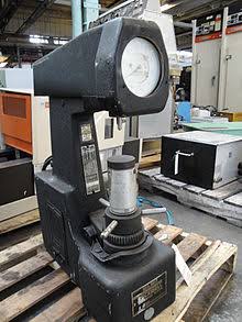
Rockwell test

Image
The Rockwell scale is a hardness scale based on indentation hardness of a material. The Rockwell test determines the hardness by measuring the depth of penetration of an indenter under a large load compared to the penetration made by a preload.     Tinius Olsen has many types of hardness testers available that can rapidly and accurately determine the hardness value of a wide variety of materials including metals, plastics, large parts, small precision parts. Whether you need are bench mounted testers, large scale floor mounted testers or dedicated testers that are integrated into your production lines, we can help you with your application. 

What is drilling machine and its types

Image
Drilling machines or drill presses are one of the most common machines found in the machine shop. A drill press is a machine thatturns and advances a rotary tool into a workpiece. The drill press is used primarily for drilling holes, but when used with the proper tooling, it can be used for a number of machining operations. The most common machining operations performed on a drill press are drilling, reaming, tapping, counterboring, countersinking, and spotfacing. There are many different types or configurations of drilling machines, but most drilling machines will fall into four broad categories: upright sensitive, upright, radial, and special purpose. UPRIGHT SENSITIVE DRILL PRESS Figure 1  Upright sensitive drill press The upright sensitive drill press (Figure 1) is a light-duty type of drilling machine that normally incorporates a belt drive spindle head. This machine is generally used for moderate-to-light duty work. The upright sensitive drill press gets its name due to th

Casting process

Image
INTRODUCTION: Manufacture of a machine part by heating a metal or alloy above its melting point and pouring the liquidmetal/alloy in a cavity approximately of same shape and size as the machine part is called casting process. After the liquid metal cools and solidifies, it acquires the shape and size of the cavity and resembles the finished product required. The department of the workshop, where castings are made is called foundry. The manufacture of a casting requires: (a) Preparation of a pattern, (b) Preparation of a mould with the help of the pattern, (c) Melting of metal or alloy in a furnace, (d) Pouring of molten metal into mould cavity, (e) Breaking the mould to retrieve the casting, (f) Cleaning the casting and cutting off risers, runners etc., (this operation is called ‘fettling’), and (g) Inspection of casting. Castings are made in a large number of metals and alloys, both ferrrous and non-ferrous. Grey cast iron components are very common; stee

Foundry

Core Making Type of cores Core Mixtures Baking of Cores Properties of Cores Core Prints Prepare Solid and Hollow Cores Use of Two Parting Surfaces Bedding in Method Moulding Techniques Loose Piece Patterns Use of Draw Back Ramming of Pattern Requiring Three Flasks Properties of the Melt Charge Cupola Furnace Tapping and Boiling Cupola Furnace Charging and Working Operation of the Cupola Furnace Bott Stick Tapping Bar Blow Holes Slag Hole Tapping Botting Clay Bott Casting Defects The Cupola Furnace Charge Zones of the Cupola Furnace Pattern Making Principles of Pattern Making Materials of Pattern Types of Patterns and Uses Allowances in Casting Draft Allowance in Casting Rapping Allowance in Casting Machining Allowance in Casting Shrinkages Allowance in Casting